
Note: This instruction Guide is for Credo units with a serial number over 4500
For previous versions download the pdf installation guides below
| Serial no. under 4500 Download PDF |
Serial no. over 4500 Download PDF |
Credo Design Features:
Wireless remote design with an encoded wireless link.
Universal vehicle connection that only needs standard trailer plug wiring on the vehicle and no hard-wired controller permanently mounted in the vehicle.
Internal load resistors to present a load to bulb sensing circuits in late model vehicles.
Buck/Boost Battery Charger means trailer battery is always charged correctly regardless of vehicle voltage.
Output protection to prevent damage from trailer wiring short circuits.
Can operate both Electric and Electric/Hydraulic Braking systems.
Real feedback of any trailer faults without specialist vehicle wiring.
Trailer stop lamps are powered when breakaway switch is activated.
Controls and eliminates flashing trailer lights caused by some vehicles when using LED lamps.
Can operate both Electric and Electric/Hydraulic Braking systems.
Real feedback of any trailer faults without specialist vehicle wiring.
Trailer stop lamps are powered when breakaway switch is activated.
Controls and eliminates flashing trailer lights caused by some vehicles when using LED lamps.
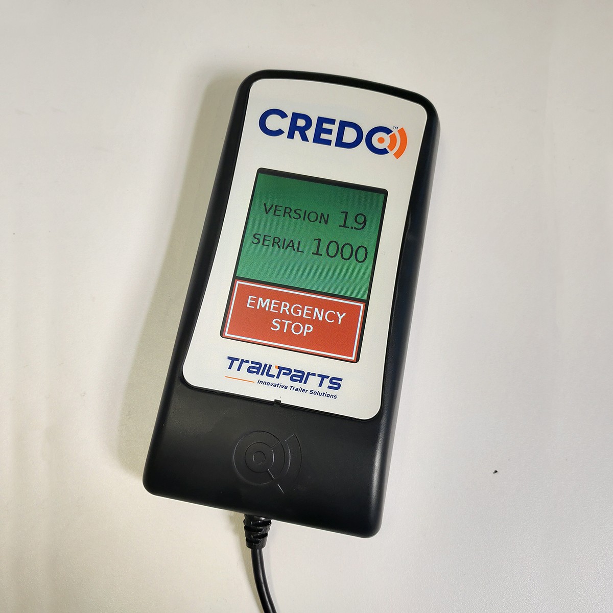
Touch Screen Controller
The In-cab controller must be connected at all times and located within easy reach of the driver.
The vehicle park or head-lights must be switched on when towing the trailer. This energizes the trailer side of the system and also will allow the trailer batteries to charge.
Check the plug and socket of the trailer and tow vehicle are securely connected and that the trailer lighting functions all work correctly. A faulty or intermittent lighting connection could mean the brakes do not operate correctly.
Ensure the break away cable is securely fastened to the vehicle.
Test the emergency brake is working. First adjust the gain control setting to read 75%. Depress emergency stop button fully, and begin to pull forwards while still holding the button down. The trailer brakes should lock the wheels.
Do not use the emergency stop feature or breakaway function as a parking brake.
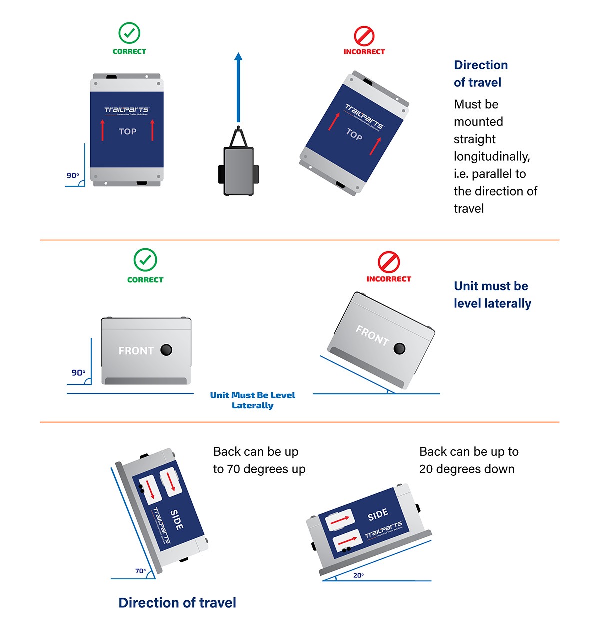
Orientation Guide
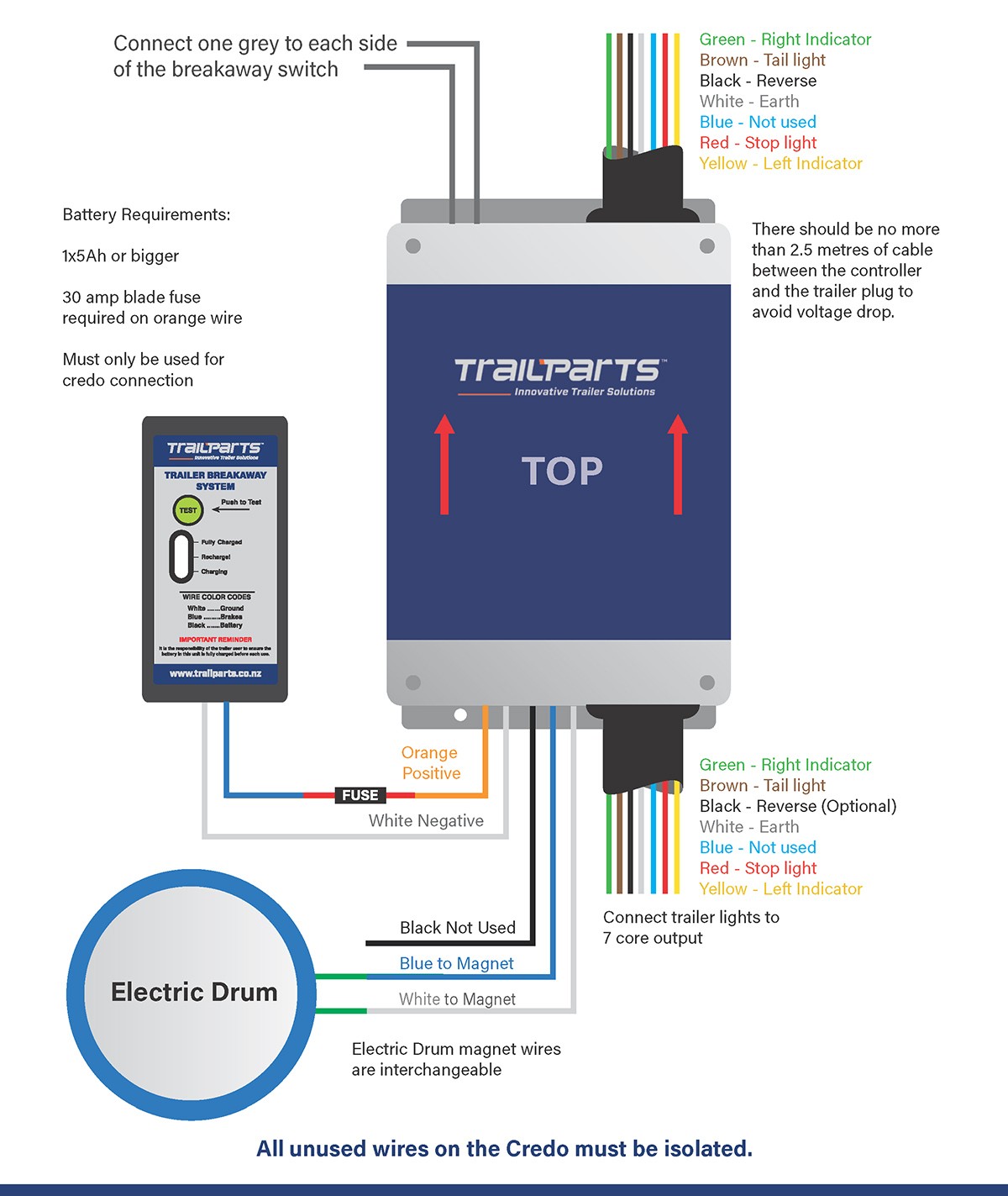
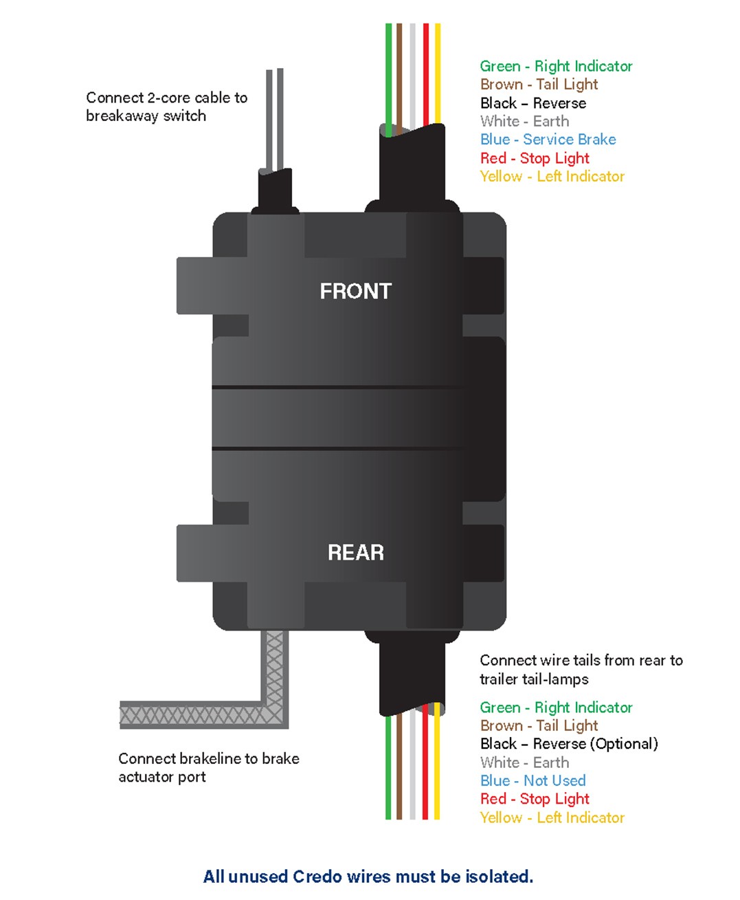
Wiring Notes:
Do not Earth to Chassis.
Keep any Electric/Hydraulic actuators as close as possible to the controller.
Keep Battery as close as possible to the controller.
Only use LED trailer lights with Credo brake controller.
Use a dedicated battery – using the brake controller battery for other systems can compromise that safety of the braking system if another fault occurs that is not related to the brakes.
Keep wiring sizes to above minimums.
| Circuit | Minimum Size | Max Length |
|---|---|---|
| Vehicle Connection* | 10A / 1.0mm² | 3m |
| Tail/Marker Lights | 5A / 0.5mm² | 10m |
| Battery | 20A / 2.0mm² | 1m |
| Electric Drums | 15A / 1.5mm² | 8m |
| Hydraulic Actuator | 25A / 4mm² | 0.5m |
*Extension from supplied length
Mounting / Installation Requirements:
Mount to a metal frame member to allow conduction of heat from load resistors away from the Credo – failure to do so means that the Credo can overheat.
Bolt to a solid frame member that will not flex during vehicle motion.
Trailer tail and marker Lights must be LED with a maximum draw of 0.6A – any additional lights will need to be connected in before the controller.
Mount the controller on the trailer draw bar with a clear line of sight to the vehicle – under the chassis or behind and or under any metallic objects that shields the controller will cause interference in the wireless signal. If using a plastic box make sure that there is a way to conduct heat away from the base of the Credo. This can be by 4 bolts connecting to a metal chassis member directly below the Credo of a significant size.
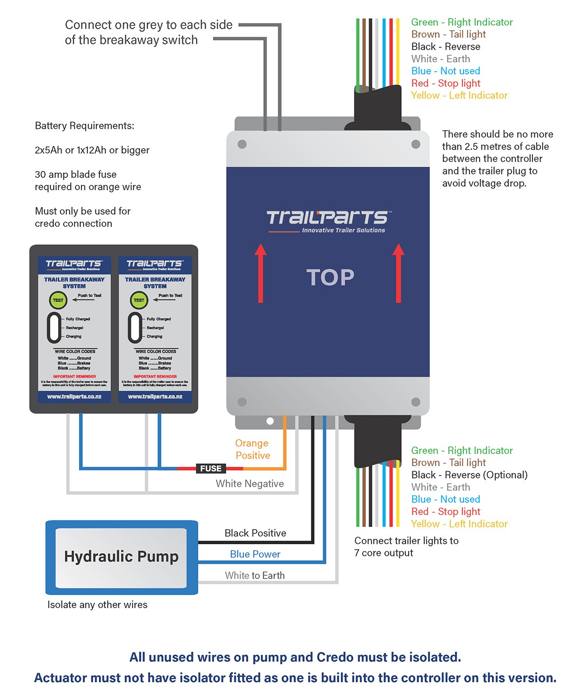
Hydraulic Wiring Diagram
Electric Wiring Diagram
Pre-Assembled Hydraulic Wiring Diagram
Commission / Testing:
Stationery Testing:
Breakaway switch
Gives 97% output which should lock the brakes to their maximum any attempt to tow the trailer should result in the wheels skidding when unladen.
Gives 97% output which should lock the brakes to their maximum any attempt to tow the trailer should result in the wheels skidding when unladen.
Emergency Stop Override Button
The brakes are applied at 75% of the current gain setting (i.e 99% gain will give a 74% brake output) different settings and brake outputs can be tried by adjusting the gain level.
The brakes are applied at 75% of the current gain setting (i.e 99% gain will give a 74% brake output) different settings and brake outputs can be tried by adjusting the gain level.
Road Testing:
Empty Trailers start with 25% Gain and Sensitivity of 3. Adjust to suit as you drive.
Loaded Trailer start with at least 50% Gain and Sensitivity of 3 and adjust to suit.
Empty Trailers start with 25% Gain and Sensitivity of 3. Adjust to suit as you drive.
Loaded Trailer start with at least 50% Gain and Sensitivity of 3 and adjust to suit.
General Notes:
The trailer should not be holding the vehicle back or ‘pulling’ the vehicle when the brakes are used. If so the brakes will be experiencing excessive wear and load.
Electric Drums may need bedding in when new or replaced. This can be done setting the Gain to about 30-35% and holding the emergency stop for approx. 0.5km while travelling at 40-50kmh. Do this in a quiet area where there is little other traffic.
Troubleshooting
Fault |
Possible Causes |
Repairs/Checks |
|---|---|---|
| In-cab controller shows
‘Low Trailer Battery’ warning (old style In-cab Controller shows Eb Error) Or No tail lights / tail lights go out when brakes are applied. |
|
|
| In-cab controller shows
‘Please Drive with Your Headlights On’ message, even though the headlights are on. (old style In-cab shows Ec Error). |
|
|
| Brakes randomly come on and lock up. |
|
|
| Braking output on In-cab controller stays at ‘--‘ on the screen when brakes are applied. |
|
|
| In-cab Controller shows ‘00’ or higher numbers when brakes applied but no braking happens. |
|
|
| Wheel locking up on one side of the trailer. |
|
|
Warranty Terms and Conditions
LIMITED 18 MONTH WARRANTY CONDITIONS
Trailequip Ltd warrants that the mechanical and electrical components of the TRAILPARTS/CREDO products as listed below will be free of defects in material and workmanship for a period of eighteen months from the original date of purchase.
Whilst we take every effort to ensure compatibility with all known vehicles we cannot guarantee 100% compatibility for all vehicles.
To obtain any warranty service, you must provide Trailequip Ltd with proof of purchase, such as a copy of your tax invoice or purchase receipt, which will include a purchase date and the serial number of your product. This warranty does not cover the removal or re-fitting of the product.
TRAILPARTS/CREDO will, at its discretion, repair, replace or refund the purchase price of a defective product or component, provided you return the defective product or component during the warranty period, freight charges prepaid, to Trailequip Ltd or to an authorized TRAILPARTS/CREDO dealer or stockist. Attach your name, address, email address, telephone number, a description of the problem, and a copy of the tax invoice or purchase receipt listing the date of purchase and the TRAILPARTS/CREDO serial number of the defective product.
This warranty does not apply if the product has been damaged by misuse, overloading, impact, modification, improper installation. This warranty is void if any TRAILPARTS/ CREDO serial number has been removed, altered, or defaced.
Please contact the below for warranty service or support:
TRAILPARTS/CREDO
C/ Trailequip Ltd
2 Tuna Street
Dargaville 0310
New Zealand
New Zealand Phone: 0800 487 245
International Phone: +649 439 5508
Australia Phone: 1300 538 598